|
This information completes the AP-3 Quick Start Flyer packaged with the kit.
Installation overview
Install the hardware according to the Quick Start Flyer. The following steps identify the basic process for installation.
- Verify kit contents, and record AP-3 information.
- Assemble the mounting plate, power supply, and processor module.
- Insert the PC Card(s) and connect the network interfaces.
- Mount the cover plate.
- Insert the CD-ROM and follow the initialization instructions.
Hardware kit contents
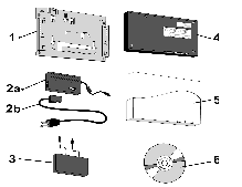
Your AP-3 kit includes the following components, similar to those depicted in Figure 3-1. (Serial Port Adapter and hardware bag not depicted.)
- Mounting plate and hardware to mount the AP-3 unit.
- a. Power supply (not included with Active Ethernet units).
- b. AC power Cord (not included with Active Ethernet units).
- Active Ethernet Splitter.
- Processor Module.
- AP-3 cover.
- Installation CD-ROM.
Figure 3-1: AP-3 Kit contents

PC Cards
To operate an AP-3, you will need at least one standard Avaya Wireless PC Card. PC Cards are not included with your kit and must be ordered as separate items. The standard Avaya Wireless PC Card is a wireless network card with integrated radio modules and antennas (2.4 GHz). The card complies with the IEEE 802.11b and Wi-Fi ™ standards on wireless LANs. Unpack the PC Card(s) and verify that all items are present as described in the user's guide that came with your PC Card kit.
Record your product information
Before you proceed with your AP-3 placement and installation:
- Copy the Site Information Form from "Documenting Your Configuration" and write down the information on the form.
- Keep the form available for future use. For example, to identify a specific unit when configuring it, or to provide details to Avaya Wireless Technical Support.
- You may need the MAC Address of the AP-3 for configuration. Locate and record the serial number and MAC address, printed on a small label (depicted in Figure 3-2) at the top right side of the processor module.
Figure: Identification Label

Mounting Guidelines
 |
The unit is not designed for ceiling mounting.
|
Mount the AP-3 on a vertical surface (such as a wall), or place the unit on a flat surface (such as a table or cabinet). Before you mount the AP-3 to a fixed location, consider performing a site survey to determine optimal placement for your unit(s).
Observe these requirements when mounting the unit:
- If not using Active Ethernet, connect the unit to a grounding type AC wall outlet (100-240 VAC), using the standard power cord supplied with the unit.
- Placement must allow for easy access to disconnect the unit from the AC wall outlet if necessary.
- Do not cover the unit or block the airflow to the unit with any other objects.
- Keep the unit away from excessive heat and humidity and keep the unit free from vibration and dust.
- Installation must at all times conform to local regulations.
- Customer provided Cat 5 Ethernet cable shall be Plenum rated if the unit is installed above a false ceiling, and the cable must never exit the building.
 |
If you want to connect the AP-3 to an outdoor antenna system,
consult the documentation that came with the outdoor antenna kit
for additional regulatory information, safety instructions, and
installation requirements.
|
Indoor antenna placement
The integrated antenna of your PC Card performs best in an open environment with as few obstructions as possible. To ensure the best performance: - Place the AP-3 as high and as centrally as possible relative to nearby wireless clients.
- When using two PC Cards, one PC Card should have an external antenna that is placed at least 2 meters away from the AP-3 to reduce the effects of normal radio interference.
- Do not conceal the external antenna.
Outdoor antenna placement
The AP-3 device has been designed for indoor placement. You can connect the device to an outdoor antenna installation using an optional antenna kit. Refer to the antenna installation guide for instructions on selecting the proper antenna.
Power up the AP-3
The AP-3 power supply accepts any input AC voltage in the range of 100-240 VAC.
 |
For your own safety, use only the power cord supplied with the unit.
Insert it in a grounded AC outlet. When using the unit in combination
with outdoor antennas, the grounding of the AC outlet must be
connected to the safety grounding system of the outdoor antenna
system and the lightning arrestor.
|
When using Active Ethernet, which supplies power over the Ethernet cable, the AP-3 is not connected to a local power outlet. For more information about Active Ethernet, contact your reseller.
LED Indicators
When powered on, the AP-3 performs start-up diagnostics and the POWER LED flashes green to indicate a successful hardware test, or glows red if the test is unsuccessful. When start-up has finished, the indicators show status. The following table shows status when the AP-3 is fully configured and running properly.
Table: Normal LED Indications
| POWER
| ETHERNET
| PC CARD A
| PC CARD B
|
Green
| Green Flash with data activity
| Green Flash with data activity, or Off if no card present
| Green Flash with data activity, or Off if no card present
|
|


